

| Home |
 CMM2000 - On-Line Manual
| Cams CMM2000 |  |
![]()
This document and diskettes or magnetic tapes contain information as reserved property, protected by the rights of the author. All the rights are reserved.
No part of this book can be reproduced in any form or by any means, or stored in a database or retrieval system, (that is except to be saved as for safety back-up purposes) or translated in other programming languages or in another language without the prior written permission from CAM SOFT s.r.l.
The information contained within this manual is subject to variations without warning.
The rights of this document, and of the diskettes and/or magnetic tapes supplied, is limited only to the reference product, it cannot be copied
and transferred to third parties without the prior consent and written permission of CAM SOFT s.r.l.
CAM SOFT s.r.l. does not provide any warranty in respect of the present material.
This manual is sold as is,without warranty of any kind, either express or implicit, respecting the contents of this manual, including but not limited
to implied warranties for the manual’s quality, performance, merchantability, or fitness for any particular purpose.
CAM SOFT s.r.l. shall not be liableto the purchase or any other person or entity with respect to any liability,
loss or damage caused or alleged to be caused directly or indirectly by this manual.
CAM SOFT s.r.l. declines every responsability derived from errors contained in this manual, or for damages (accidental or not)
derived from the supply, interpretation an use of this manual.
|
|
||
|
|
||
|
|
||
|
RADIAL Translating OSCILLATING Follower FLAT FACED Follower |
||
|
|
LINEAR Translating OSCILLATING Follower |
|
|
|
AXIAL Translating OSCILLATING Follower |
|
|
|
||
|
|
||
|
|
SPECIAL PROFILES (Intermittent Working) |
|


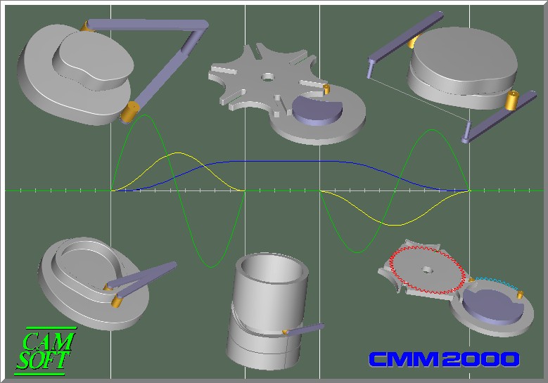
CS CMM2000 is an application oriented to the analysis of Radial Cams , Cylindrical Cams or GENEVA Wheels, STAR Wheels and INTERMITTENT Drum Mechanisms when is known the follower motion.
The design activity consist in the geometric definition of the Cam profile and, as immediate result, the check of the follower operation.
In order to create the Cam curve responding to the y = f(a) coinciding with the required y = f(t) it is supposed that the camshaft rotates at the fixed constant angular velocity ω = 2 π / t (in the case it is α = ω * t)
All the typology of the follower are tacken sthg. into account :
-
RADIAL Translating Follower
-
OSCILLATING Follower
Inside the two Follower typology are taken into account the following Follower types :
-
Roller Follower
-
Flat-faced Follower
-
Knife-edge Follower
It is possible to take into account the Follower constraint obtaining the cam contour either for positive drive or spring load. A part from any structural aspect inside the Cam drawing, CMM2000 gives exclusive reference to the kinematics aspect of the Cam.
The kinematics correlates the attended features of the Follower (position, velocity, acceleration) with those of the mover (Cam profile).
The analysis can follows two way :
-
When it is known the follower Motion Type the Cam profile, correlated with displacement, velocity and acceleration are immediately calculated.
-
When it is known the Cam profile (FILE of POINTS) are verified the Follower kinematics as displacement, velocity and acceleration.
It s necessary therefore to select the Follower type in order to correctly synthesize the Cam profile.
RADIAL Translating Follower
-
Roller Follower
The synthesized profile correspond to the track followed by the centre of the Roller.
The effective Cam profile can be obtained offsetting the synthesized Profile of a quantity
corresponding to the Roller radius or directly using the “Cutter radius Offset” on the CNC. -
Knife-edge Follower
The case is analogous to the previous but the radius of the Follower is “0” -
Flat-faced Follower
The contact point between Cam profile and the flat of the Follower change position continuously in respect to the axis of the Flat-faced Follower. The synthesized profile is generated by the group of the envelope lines of the displacements.
OSCILLATING Follower
-
Roller Follower
-
Knife-edge Follower
-
Flat-faced Follower
Each condition arranges an automatic solution introducing the Cam profile correction when are known the feature of the Cam-Follower group.

The INPUT data, to define the Cam Profile, can to be acquired with some different characteristic as :
1. Basic Curves definition
2. File of points
3. S.V.A. graphic : displacement, velocity and acceleration.
CMM2000 is interfaced with MECAD, a program oriented to kinematic motion analysis, consequently it is directly enabled to read its graphic Files of points S.V.A.
CMM2000 is also enabled to read files CMM of previous versions..
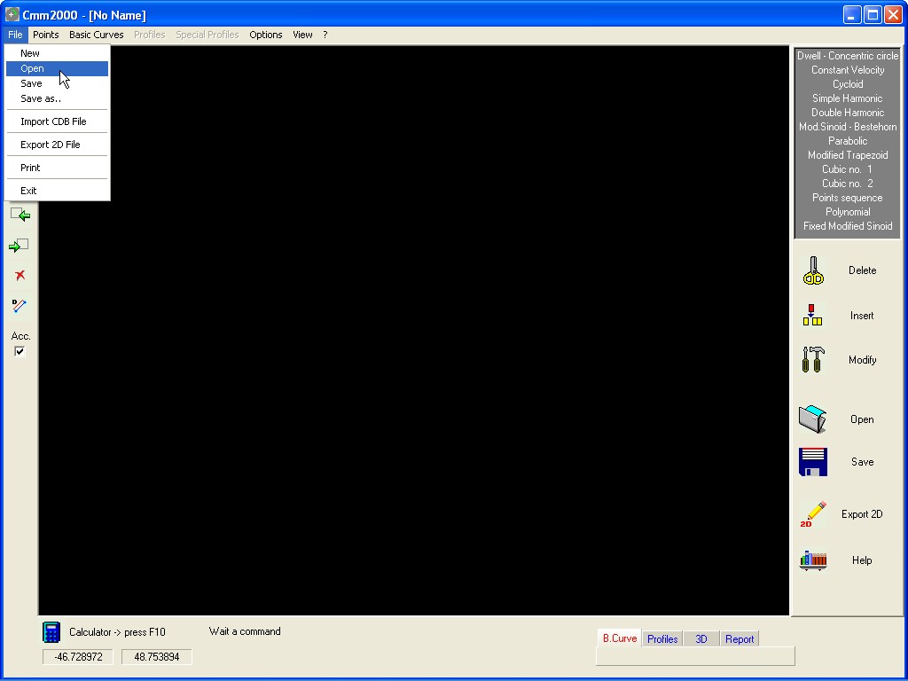
Load a file
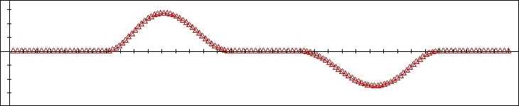
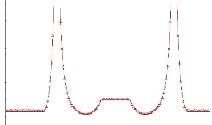
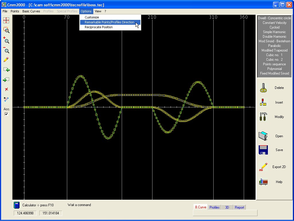
With the introduction of a sequence of Data INPUT the program generates interactively a S.V.A. graphic, with no regard to the characteristics of the Follower and the type of Cam, this graphic will be used afterwards to define the Cam Profile when will be known the structure of the Follower selected and the type of Cam .
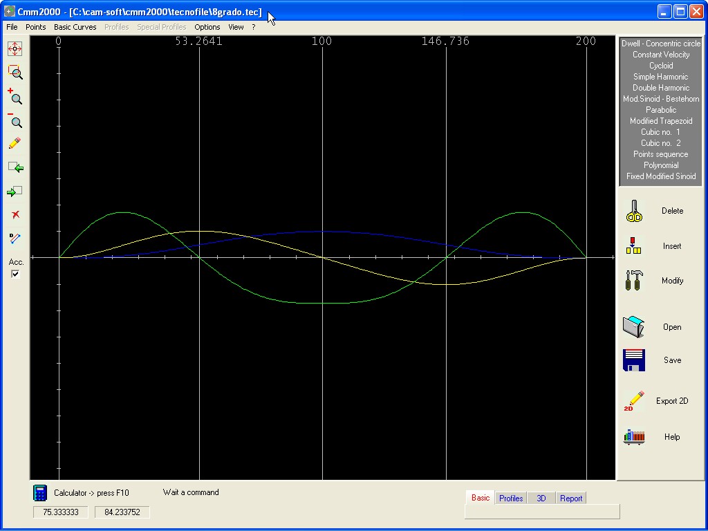
Graphic sample of a S.V.A.
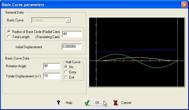
When is inserted the first Basic Curve it is possible to insert the general data of the
Cam which will appears in the upper part
of the
Dialog Box.
The required parameters are (in mm.) :
-
Radius of Base Circle for Radial Cams and Total length for
Translating Cam.
- Initial Displacement ( normally is “0”)
BASIC CURVES definition
Dwell – Concentric circle to the rotation Axes
The activity generate a dwell
stage on the Cam,
it is required the rotation angle.
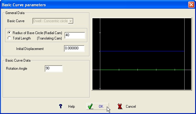
BASIC CURVE Graphic
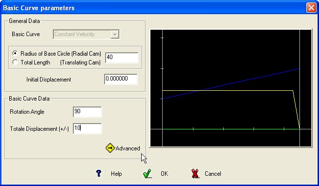
The activity generate a displacement stage
on the
Cam, climb (displacement +) or slope (displacement -) following the
Basic Curve with constant velocity of the follower and zero the
acceleration.
Required Data :
Cam Rotation Angle or length of the stage.
Total displacement of the follower (+/-)
It is suggested to
don’t use this Basic Curve for the first stage, when this is
impossible it is opportune to introduce them with a Dwell–Concentric
circle whose length must be longer than the calculation Step.
BASIC CURVE Graphic
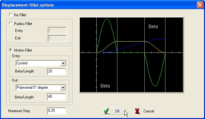
In order to reduce the acceleration peak (initial and final), it is possible insert a displacement-fillet using the Advanced options.
Two options are available :
Fillet with Radius,
fillet with Basic
Curve.
Fillet
with Radius.
Select Radius
and define its value to obtain the
fillet; the
Radius must be greater than the Radius of the roller
follower.
Fillet
with
Basic Curve.
Select the
Basic Curve to be
used,
define the angle Beta representing the width of the stretch of
fillet.
In both cases :
1) The calculus preserves
the position and the slope of the stage at Constant velocity
modifying the entry and exit to insert the fillet.
2) When the
previous Basic Curve lets the permission, it is applied a
transposition of the complete stage, including the fillet, in order
to preserve the start and exit position of the stage at Constant
velocity in respect to the preceding Basic Curve.
The stage at
Constant Velocity has preserved its position and slope while the
fillet covered a part of the preceding Basic Curve.
The
operator will decide to modify the application angle of the
subsequent Basic Curve in order to compensate the part covered by the
exiting fillet.
In the following sample are defined five Basic
Curve as :
Stage at Dwell – Concentric circle : 60°
deg.
Stage at Constant Velocity : 90° deg ; displacement 15 mm
; Beta Fillet 20° deg
Stage at Dwell – Concentric circle
: 50° deg.
Stage at Cycloid : 90° deg ; displacement -15
mm
Stage at Dwell – Concentric circle : 60° deg.
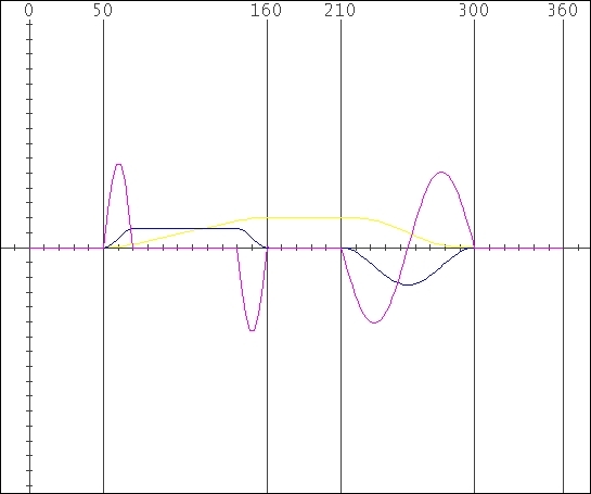
The operator can
to notice :
1)
The initial stage at Dwell
is
reduced to 50° deg ; 10° deg are engaged by the fillet.
2)
The stage at Constant Velocity including start
and exit fillet
results 20° deg greater
3)
The second Dwell stage has been defined of 50° deg rather than
60° deg to make room to the exiting fillet.
4)
The subsequent stages preserved their width and position.
Required Data :
Cam Rotation Angle or length
of the stage.
Total displacement of the follower (+/-)
BASIC CURVE Graphic
It is possible to define “Half” Basic Curve ; the division point correspond to the inflexion point of the graphic displacement.
Select the Option : No for complete Curve , Entry for entry half-curve and Exit for exiting half-curve
This Curve has a cosine
acceleration curve.
The
projection of a generic radius point P , starting at point “0”
moves vertically at point Q along the diameter D of the reference
circle with simple harmonic motion while the circle rotate at
constant ω.
Required Data
:
Cam Rotation Angle or length of the stage.
Total displacement of the follower (+/-)

BASIC CURVE Graphic
It is possible to define “Half” Basic Curve ; the division point correspond to the inflexion point of the graphic displacement.
Select the Option : No for complete Curve , Entry for entry half-curve and Exit for exiting half-curve
This is an asymmetrical curve composed of two different harmonic motions, one being one-quarter of the amplitude and twice the frequency of the other.
It has the advantages of the simple
harmonic curve
with almost complete elimination of the high shock and vibration at
the beginning of the stroke.
Required Data :
Cam
Rotation Angle or length of the stage.
Total displacement of the follower (+/-)

BASIC CURVE Graphic
It is possible to define “Half” Basic Curve ; the division point correspond to the inflexion point of the graphic displacement.
Select the Option : No for complete Curve , Entry for entry half-curve and Exit for exiting half-curve
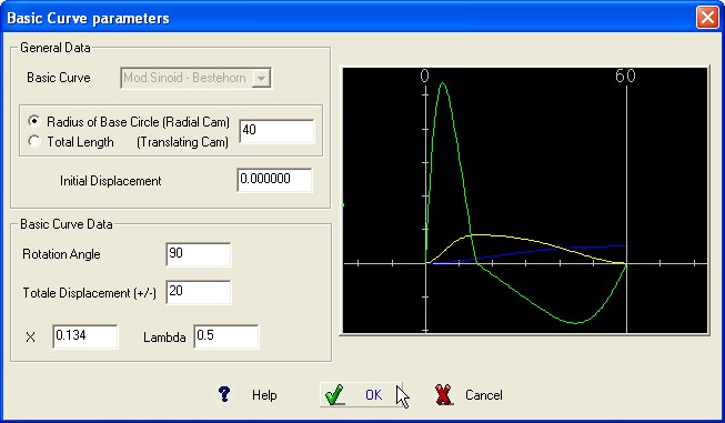
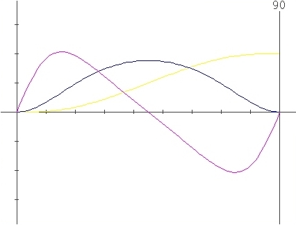
This is a modifiable sinoid using two
supplementary
parameters enabled to move the inflexion point of the graphic
displacement and the position of the maximum acceleration
value.
Required Data :
Cam Rotation Angle or length of
the stage.
Total displacement of the follower (+/-)
X parameter
Lambda (l) parameter
BASIC CURVE Graphic
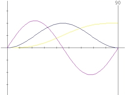
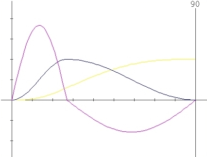
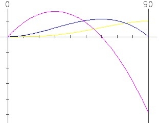
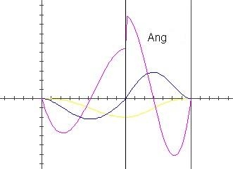
The following graphics show
the changes in
S.V.A. graphics enabled by the change of the parameters X and Lambda
values.
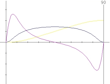
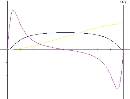
Change for X
only :
 Parameters
: X=0 , l=0.5
Parameters
: X=0 , l=0.5
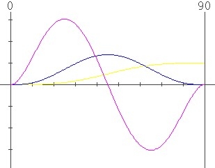
 Parameters
: X=0.134 , l=0.5
Parameters
: X=0.134 , l=0.5
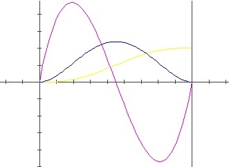
 Parameters
: X=0.41 , l=0.5
Parameters
: X=0.41 , l=0.5
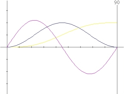
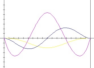
 Parameters
: X=0.5 , l=0.5
Parameters
: X=0.5 , l=0.5
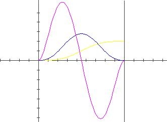
Change for Lambda only :
 Parameters
: X=0 , l=0.5
Parameters
: X=0 , l=0.5
 Parameters
: X=0 , l=0.3
Parameters
: X=0 , l=0.3
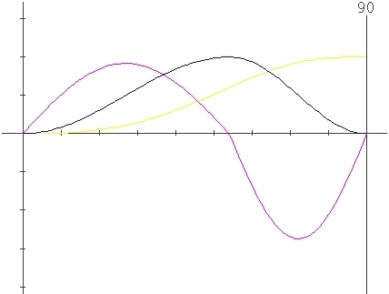 Parameters
: X=0 , l=0.6
Parameters
: X=0 , l=0.6
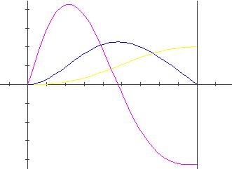
Sample with
simultaneus variation of X and Lambda parameters
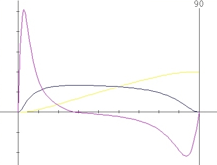 Parameters
: X=0.5 , l=0.3
Parameters
: X=0.5 , l=0.3
Parabolic
or constant acceleration
This is
a curve of polynomial family and has constant positive and negative
acceleration values. The curve has the smallest maximum accelerations
for all curves possible.
Required Data :
Cam Rotation Angle or length
of the stage.
Total displacement of the follower (+/-)

BASIC CURVE Graphic
Modified
Trapezoidal
This
is a curve composed of a parabolic motion combined with the cycloidal
curve.
Required
Data :
Cam Rotation Angle or length of the stage.
Total displacement of the follower (+/-)
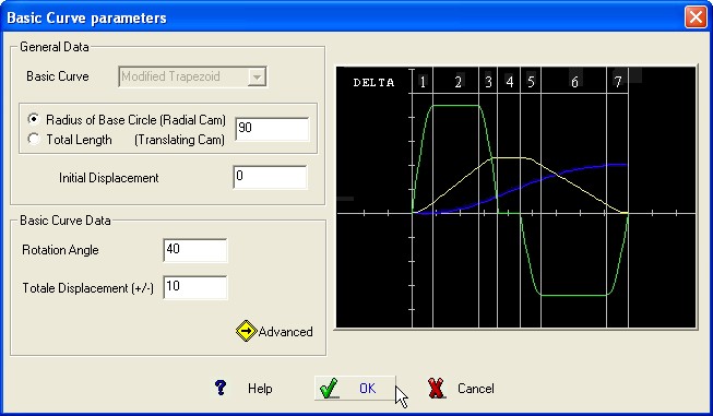
BASIC CURVE Graphic
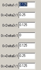
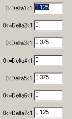
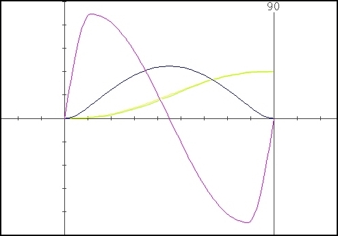
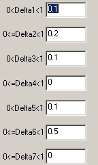
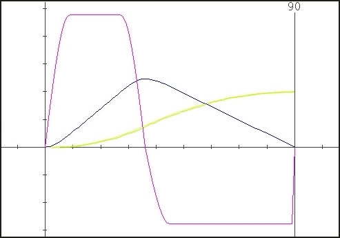
The
“Advanced”
option enable the possibility to define the width of elementary
stages. The default values define a symmetric trapezoidal curve but
it is possible to obtain various configurations changing the
parameters “Delta” defining the seven percentage width of
the elementary stages; instead of “Percentage width” the
operator can use directly the elementary stage amplitude in deg. In
the first case the sum of the elementary Percentage width must be
1.00 , in the second case the sum of the elementary width must be
equal to the total Cam Rotation Angle.
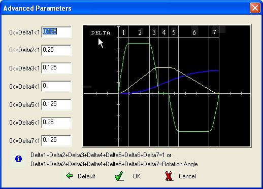
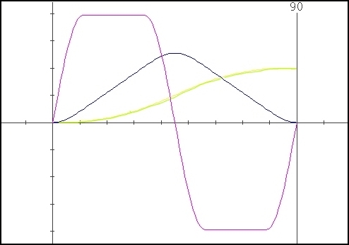
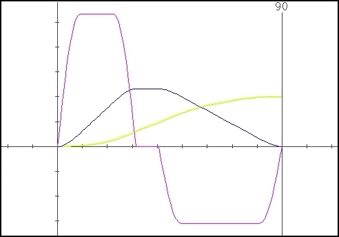
Some samples obtained using different values for the parameter “Delta” :

Cubic
no. 1 Curve
This is a curve
of
polynomial family and has a triangular acceleration curve. It is a
modification of the parabolic curve, eliminating the abrupt change in
acceleration at the beginning and the end of the stroke. However it
does have an acceleration discontinuity at the midpoint.
Required Data :
Cam Rotation Angle or length
of the stage.
Total displacement of the follower (+/-)
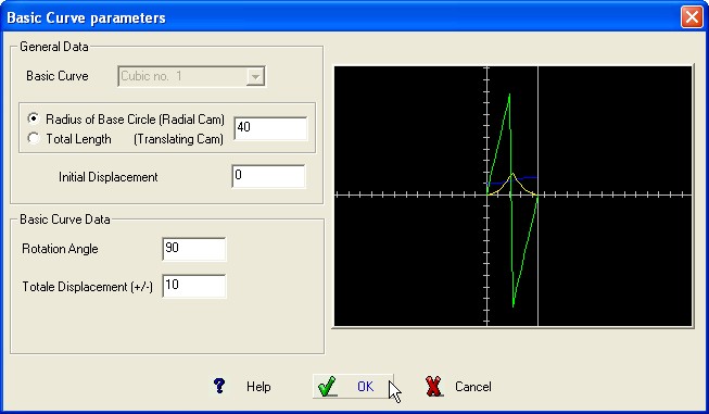
BASIC CURVE Graphic
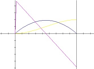
This curve is similar to the Constant
Acceleration
and the Cubic n.1. It differs from these, however, in that there is
no
discontinuity in acceleration in the transition point and also
in that its acceleration is a continuous curve for the complete rise.
Required Data :
Cam Rotation Angle or length
of the stage.
Total displacement of the
follower (+/-)

BASIC CURVE Graphic
This curve suppose that the operator has a
sequence
of points defining the Cam profile.
The activity requires the
operator to introduce a sequence of coordinates of points, in the
canonic format, defining the profile he will use.
See also the
command of the Menù “Points”
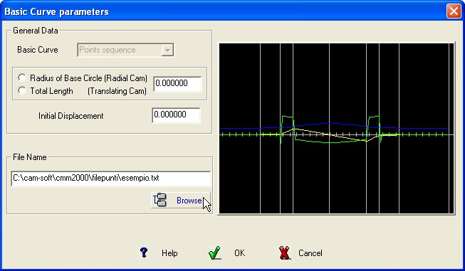
BASIC CURVE Graphic
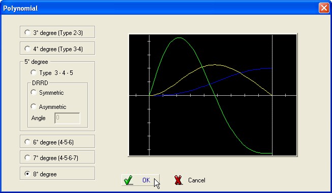
This solution enable the operator to
select one of
the available solution.
Required Data :
Cam Rotation
Angle or length of the stage.
Total
displacement
of the follower (+/-)
It is now necessary to gain access in
“Advanced” to select the Polynomial
Type required.
|
Type 2-3 (3th degree) |
Type 3-4 (4th degree) |
|
Type 4-5-6 (6th degree) |
Type 3-4-5 (5th degree) |
|
Type 3-4-5 (5th degree) DRRD symmetric |
Type 3-4-5 (5th degree) DRRD asymmetric |
|
Type 4-5-6-7 (7th degree) |
8th degree |
It is possible to define “Half” Basic Curve ; the division point correspond to the inflexion point of the graphic displacement.
Select the Option : No for complete Curve , Entry for entry half-curve and Exit for exiting half-curve
The
Fixed Modified Sinoid curve is a combination of two quarter of
cycloidal curve and a complete sinoid curve.
This curve is a good
choice in moving large masses. The modified sine curve, for lower
torque and power demand, is one of the best choice of curves.

BASIC CURVE Graphic
It is possible to define “Half” Basic Curve ; the division point correspond to the inflexion point of the graphic displacement.
Select the Option : No for complete Curve , Entry for entry half-curve and Exit for exiting half-curve
This function enables the
program to import a
File generated with a previous version of CMM
Select
the file to be imported inside the Dialog Box appearing on the
monitor.
When , in the sequence, is requested a File of Point
appears a message requiring the conversion.
In this case use the
command “Convert
from CMM”
in the menù Points
and repeat the operation.
This function enables the
program to obtain the
Follower motion characteristics from any profile saved in DXF or MI
format.
The file CAD must contain only the geometric informations
of the profile completed with a point defining the start point of the
profile.
( the files C:\cam-soft\cmm2000\cad\dxf
\Rettangolo.dxf and
C:\cam-soft\cmm2000\cad\mi
\Policentrica.mi are
useful
examples).
Click the option “Graphic displacement”
when the drawing MI or DXF already expresses the displacement trend
of the follower and not the shape of the Cam (see the file
C:\cam-soft\cmm2000\cad\mi
\Alzate.mi ).
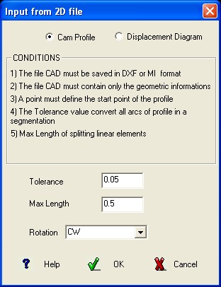
Insert the required data
specifying the chordal
tolerance to be used to convert all the circle arcs in a
segmentation, the max distance from two adjacent points and the
direction to follow the profile.
Using the graphic obtained for
V.S.A. it is now possible to define the shape of the Cam when are
known the complete characteristics of the follower.
Example
: Cam obtained from the file Rettangolo.dxf.
Using the
command Create/Modify inside the menù Points
is
gained the access to the windows enabled to operate on Files of
Points.
It is possible to Edit an existing File or create a
new using the command “NEW” or “Y=FUN(X)”
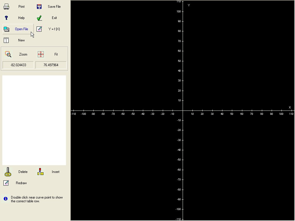
Operations on File of Points
Enable the Operator to insert
a mathematics
function to generate the point of the file.
Example
: Y=SIN(X).
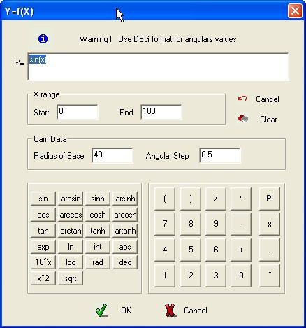
Y=f(X)
Are required : The
value of Radius of Base , the value of starting assigned to the
independent variable and the value final assigned to the independent
variable.
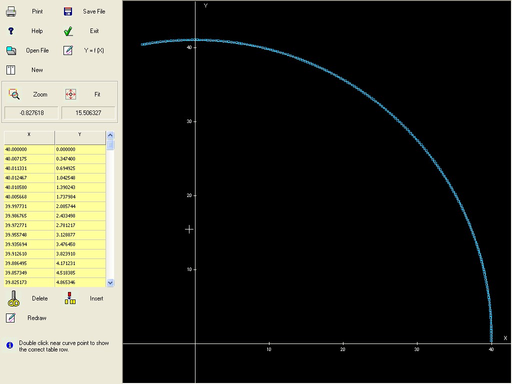
When a File is loaded or created as new, the
coordinates are graphically presented, it is possible to modify the
values acting on the commands appearing at the left of the window.
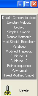
MENU’ BASIC CURVES
(Top
bar)
This Menù enables the command consenting to modify or
change the defined Basic Curves.
Available
Options
:
DELETE
BASIC CURVE
The
command delete the Basic Curve selected with a click on the S.V.A
graphic included into the application stage.
INSERT
A BASIC CURVE
Click on the S.V.A graphic included into the application
stage before which insert the new Basic Curve.
Select the type of
the new Basic Curve and insert the required data.
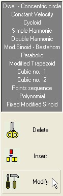
MODIFY
THE BASIC
CURVE
Click on the
S.V.A graphic
included into the application stage of the Basic Curve to be
modified, select a new Basic Curve or change the parameters of the
current Basic Curve.
To modify the general data of the Cam click on the graphic S.V.A. of the first Basic Curve; in this case it is possible to modify the Base Radius and the Ramp (Total displacement).
This
Menù enable the possibility to insert one or more point on the
graphics S.V.A.
It
is required the angular position of the new point, immediately the
point is inserted on the graphic of displacement, velocity and
acceleration.
When in the required position already exist a point
the command is ignored.
If after the insertion of some new
point, one or more Basic Curve are modified, the program
automatically calculates the new correspondences on the modified
S.V.A. graphics.
Also in this case when one recalculating
correspondence coincide with an existing angular position coming from
the change of the Basic Curve the command is ignored.
To
cancel the inserted points use the command Delete Point of the same
Menù.
It possible to modify the graphics S.V.A. intervening graphically only on the displayed curve of the displacement. Selecting the command will appear a pull-down menù where may be selected the option :
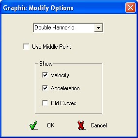
· Select the Basic Curve to be used into the interval of the modification, are only available Double Harmonic and Cycloid
· May be enabled the selection of the middle point of the interval as pilot-point of the modification
· Select which other curve must be visible (velocity, acceleration) during the modification of the displacement
Confirm the section pressing the key OK, indicate the two extreme point including the modification plus the internal point that will control the interactive modification.
If
no error is contained in the data it possible to drag the curves
included into the selected interval, all the curves will be moved as
congruent rubber-line following the position of the mouse.
It is
possible to interrupt the procedure, in any moment, using the key
![]() ,
to confirm the change
,
to confirm the change
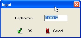
press the left button
of the mouse if the displacement must coincide with the current
position of the mouse pointer OR the right button of the mouse if it
is requested a precise value of the displacement, in this case will
appear a DialogBox in which write the precise value of the
displacement, press OK to confirm.
Note : Redefining the Basic Curve interested by an interactive modification, the modification will be lost. Instead it is possible to intervene on the previous and following Basic Curve.
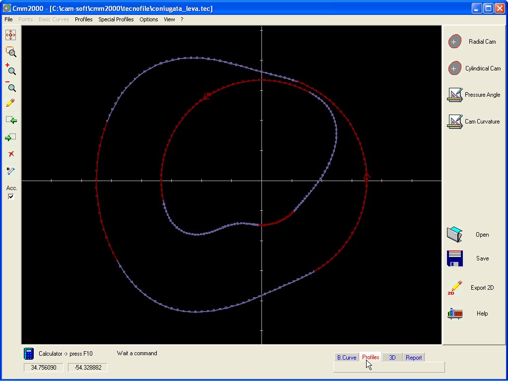
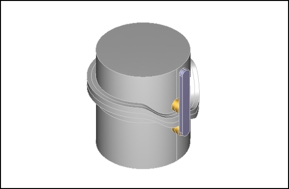
Window Profiles
Inside sub-menù are present the following Options :
RADIAL CAM / TRANSLATING CAM / CYLINDRICAL CAM
Starting from the Data INPUT the Profiles of a Radial Cam,
Translating Cam, Cylindrical Cam are respectively calculated.
Select
the structure of the follower and insert the required Data.
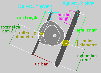
Ex. Radial Cam with OSCILLATING Follower and balancing frame.
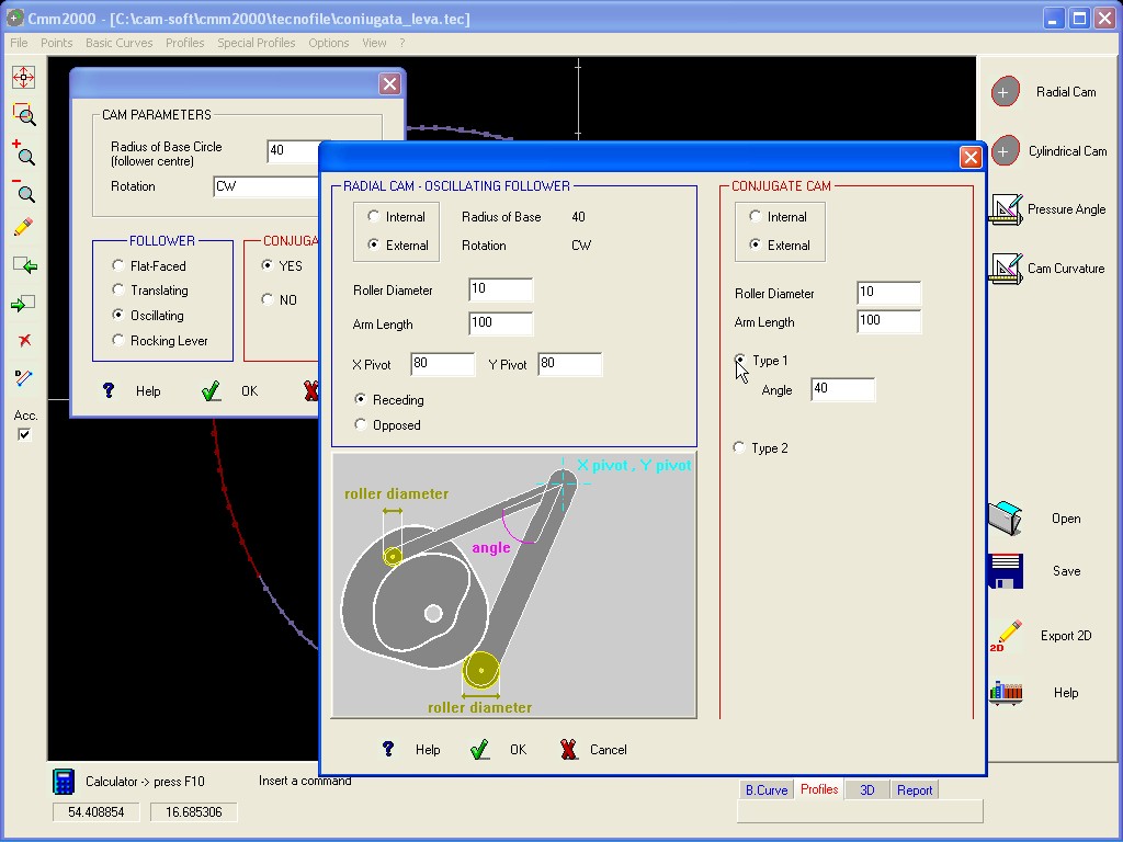
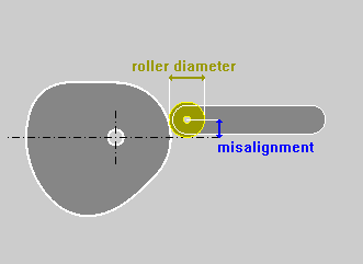
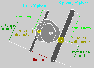
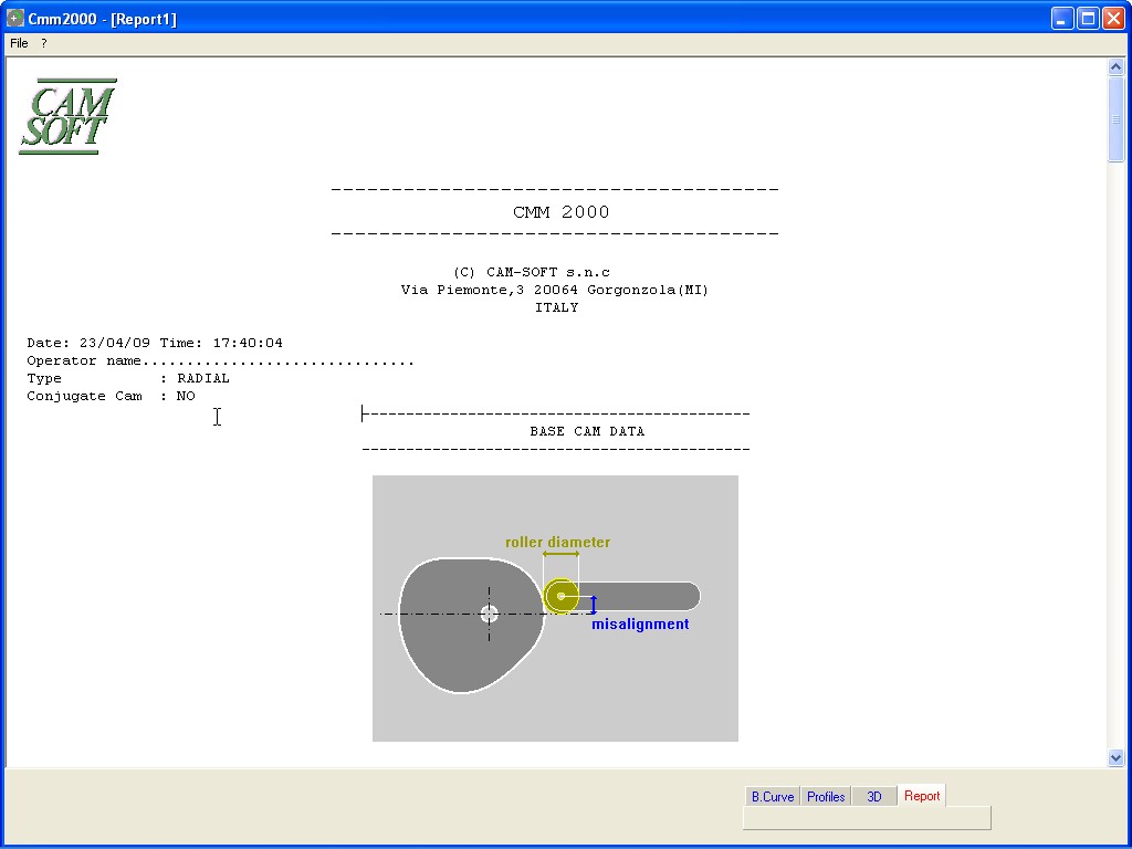
CONJUGATE CAM / MISALIGNED FOLLOWER
For
a Radial Cam, and where admitted, it is possible to calculate the
Conjugate Cam profile and/or the Cam profile using a misaligned
follower :
RADIAL
Translating
Follower :
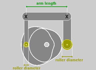
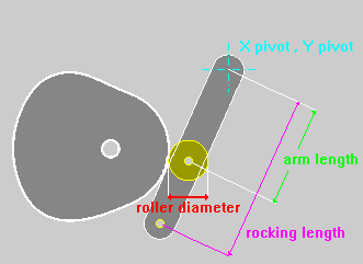
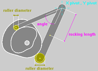
OSCILLATING
Follower :
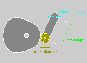

The Option Roking Lever enables the calculus of the Cam Profile inserting the motion characteristics in respect to the point of application of the Follower instead of the point of application of the Roller.
The length of the Roking must be Negative when the point selected for the definition of the motion characteristics is in an opposite position to the Roller in respect to the Pivot Point.
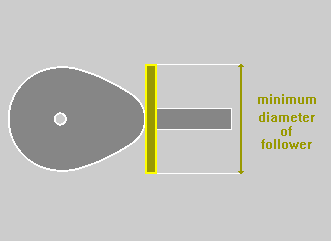
FLAT
FACED Follower :
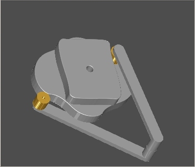
Selecting
one of the Option : Cam Profile Internal
/ External
it is possible to obtain the Solid
Models as
represented in the
following images.
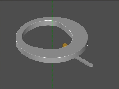 Internal
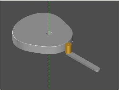 External
Coordinating the Type of Cam (Internal / External) with the structure of the frame defining the Conjugate Cam, it is possible to obtain all the types of Desmodromic Cams (external track / internal track, etc.)
 “Desmodromic”Cam
defined with Radial Cam
Internal and Conjugate Radial Cam External.
“Desmodromic”Cam
defined with Radial Cam
Internal and Conjugate Radial Cam External.
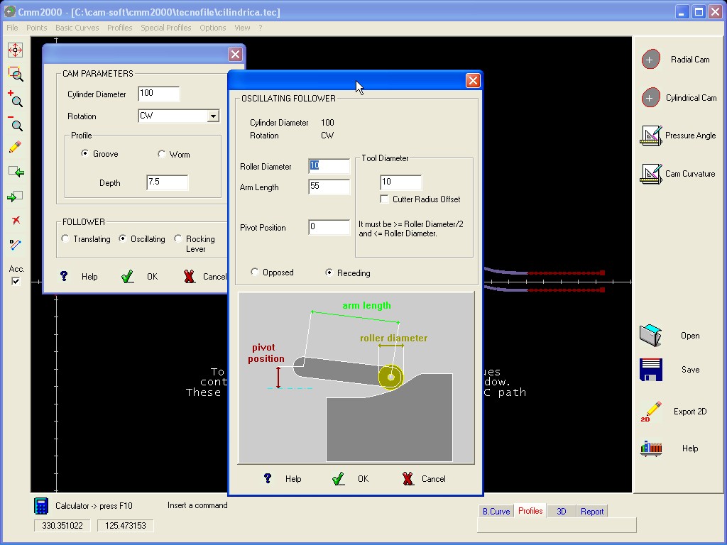
Inside the Dialog Box defining the CYLINDRICAL
CAM it is
possible to define the
Diameter of the Tool and enable / disable the option to use or not
the Cutter Radius Offset on the CNC.
These conditions are used
for Data calculation of the the Tool Path in order to work the Cam on
a CNC machine.
Notes :
For
the case only of Cylindrical Cam with RADIAL
Translating Follower,
worked with a
tool having the same diameter of the Roller it is possible to use the
2D Profile exportable from the window Profiles.
In
all the other cases there are necessary further specific informations
as follows :
Case 1.
The
operator gives : Roller
Diameter = 0
and Tool
Diameter =
0
It is a limit case, it is
generated only a Cam Profile representing the track of the centre of
any Roll for any tool diameter. Inside the window Data
are
presented
the informations regarding the tool centre, used for the CNC in the
format : Angle, X,
Y, Z
The Option : Use
the “Cutter
Radius Offset” has no
effect.
Case 2.
The operator gives : Roller
Diameter ≠ 0 and
Tool
Diameter = Roller Diameter
Inside
the window Profiles will appear two Profiles representing the Upper
Cam Profile and the Lower Cam Profile. Inside the window Data
are
presented
the informations regarding the tool centre, used for the CNC in the
format : Angle, X,
Y, Z
IMPORTANT :
It
is impossible to mill the Cam Profile with a tool having a different
Diameter in respect to the Roller Diameter previously defined.
The
Option : Use
the “Cutter
Radius Offset” has no
effect.
Case
3.
The operator gives : Roller
Diameter ≠ 0 and
Tool
Diameter defined
as follows :
Roller Diameter >
Tool
Diameter > Roller Diameter / 2
The
Option : Use
the “Cutter
Radius Offset” is Disabled
Inside
the window Profiles will appear two Profiles representing the Upper
Cam Profile and the
Lower Cam Profile.
Inside the window Data
are
presented
the informations regarding two tracks for the tool centre,
used
for the CNC in the format :
Angle,
X, Y, Z regarding
the milling of
the lower track of the Cam Profile.
Angle,
X, Y, Z regarding
the milling of
the upper track of the Cam Profile.
IMPORTANT
: It is
impossible to mill the Cam
Profile with a tool having a different Diameter in
respect to the
Tool Diameter previously defined.
The
Option : Use
the “Cutter
Radius Offset” is Enabled
Inside
the window Profiles will appear two Profiles representing the Upper
Cam Profile and the Lower Cam Profile.
Inside the window Data
are
presented
the informations regarding two tracks on the Cam Profile, used for
the CNC in the format :
Angle,
X, Y, P, Q, Z regarding
the
milling of the lower track of the Cam Profile.
Angle,
X, Y, P, Q, Z regarding
the
milling of the upper track of the Cam Profile.
Note
: Since the
Data are regarding the
nominal Track surface of the Cam Profile, it is possible to use any
tool diameter
< Roller Diameter.
It
is also important :
a
) The CNC must
be enabled to
use the function G41, G40, G42 (Enabling Cutter Radius Offset)
jointly the use of a Rotating Axe; in this case use Data in the
format Angle,
X, Y, Z
.
b ) The CNC must
be enabled to
use, in parametric mode,
the values assigned to P
and
Q
indicating
the parametric corrections for X
and Y
;
in this case use Data in the format Angle,
X, Y, P, Q, Z
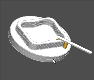
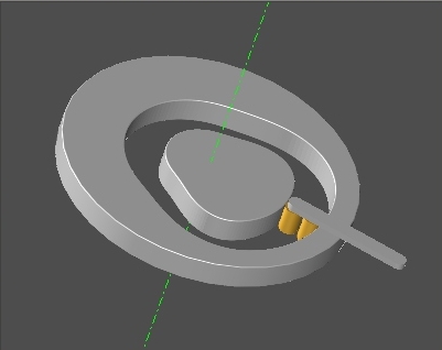
 CYLINDRICAL CAM,
AXIAL
Translating
Follower, Rib Cam Profile
CYLINDRICAL CAM,
AXIAL
Translating
Follower, Rib Cam Profile
PRESSURE ANGLE and CAM Curvature
This
function display the Graphics of the Pressure Angle and Cam curvature
of the calculated Cam Profiles.
Graphic : PRESSURE ANGLE and CAM CURVATURE
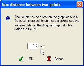
The function generates the thicken of the active Cam Profile
inserting new points belonging on the same spline.
The thicken
has no effect on the graphics S.V.A. To obtain more points on these
graphics use the variable defining the Angular Step calculation
inside the file INI.
Insert the value defining the max
distance between two adjacent points belonging on the Cam
Profile.
All the elements, having length grater than that defined,
are splitted in two or more parts.
SPECIAL
PROFILES (Intermittent Working)
This
menù includes all the commands allowing the definition of
Intermittent workings mechanisms.
These mechanisms don’t uses for the follower Cam basic curves,
therefore during the definition no graphic S.V.A. is represented.
GENEVA WHEELS
For the definition the required Data
are :
Number
of Turnover station
Distance between centres of mover and Geneva
Wheel
Pin diameter
R.P.M. of the Mover.
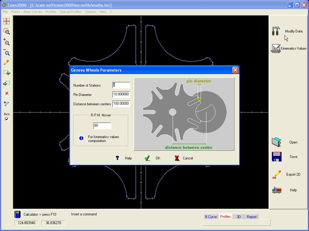
The available Output are similar to these of the Cam.
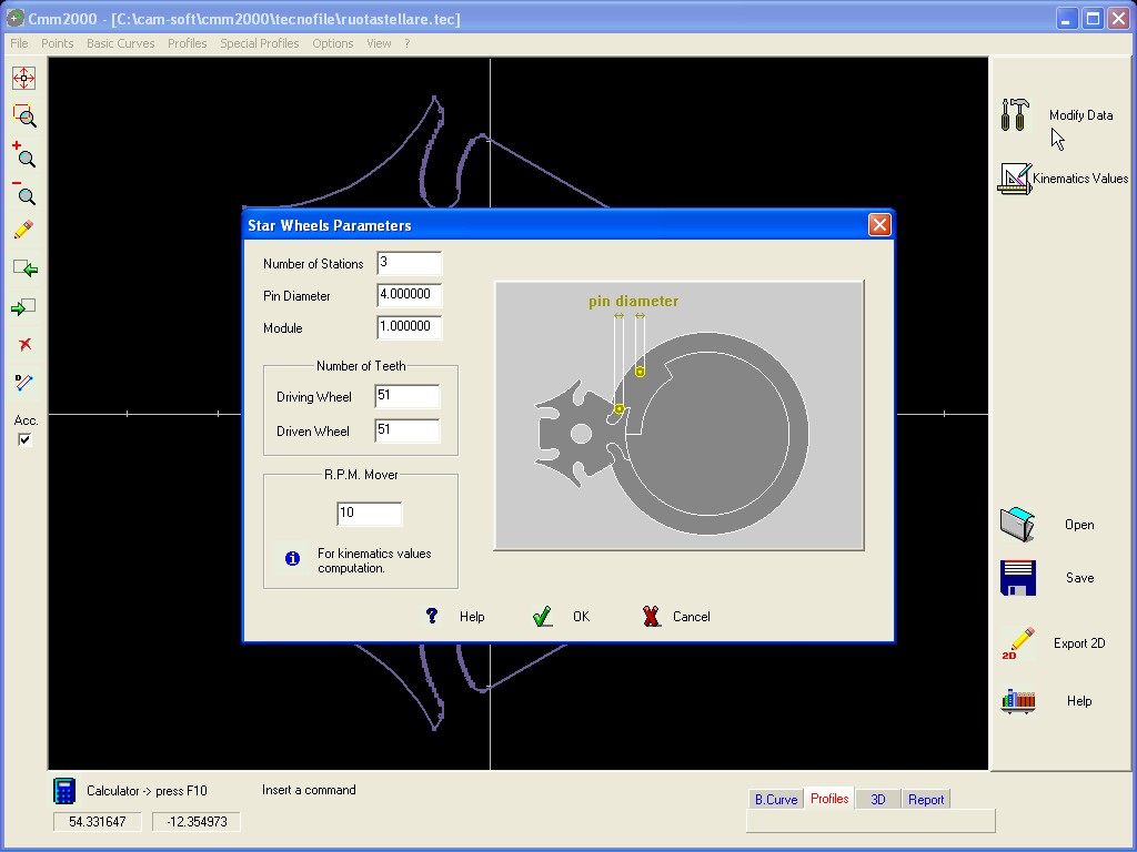
STAR WHEELS
The
working operation is like the Geneva Wheels it is added a couple of
gears.
For
the definition the required Data are :
Number of Turnover
station
Pin diameter
Module m0
Number
of Teeth for Z1
Number
of Teeth for Z2
R.P.M.
of the Mover
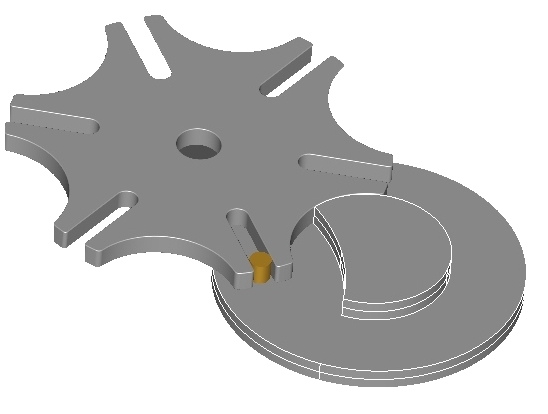
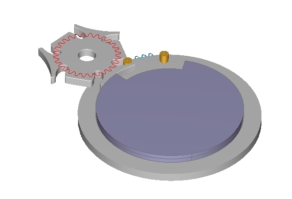
All the profiles necessary to the
mechanism
construction are completely defined.
The movements can be
simulated in the window 3D.
Inside the window Basic Curves it is possible to export the 2D
drawing in the format .DXF or .MI
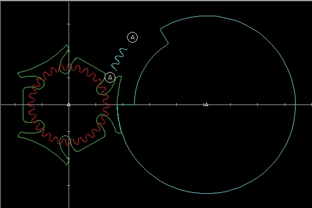
The available Output are similar to these of the Cam.
The following Options are available :
Enable
/ Disable the presentation of Remarkable points (vertex of
elements).
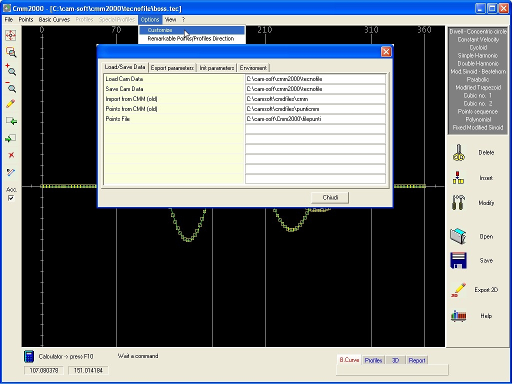
Enable
the configuration of the parameters inside File INI in order to
customize the program running.
As Maximum
Angular Step in
calculation and Max
Step Millimeter in
calculation,
important parameters in definition Cam Profile.
Variable inside the configuration file CMM2000.INI
defining the Max calculation angular
Step along
the Cam Profile.
Step Millimeter
Variable inside the configuration file CMM2000.INI
defining the Max calculation distance
[mm] between
two adjacent point, it change the max angular Step when it results
greater than the distance.
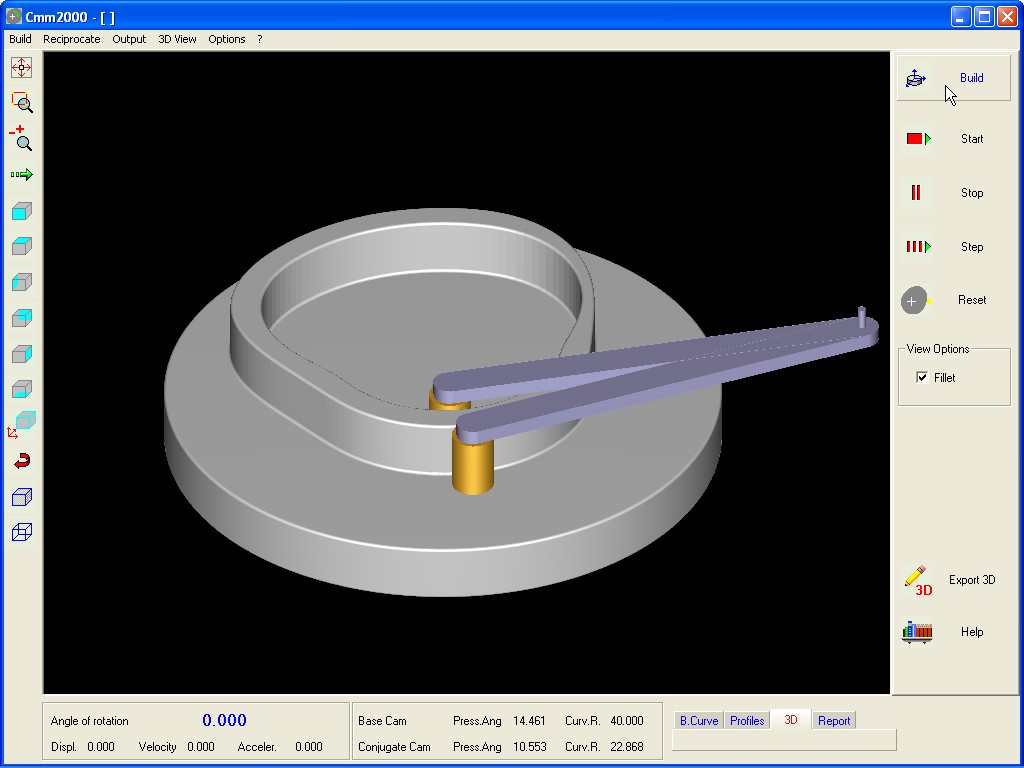
It operates the 3D visualization of processed Cam and simulates the Cam movement in respect to the defined Follower frame. Use the command to start / stop rotation , step to step rotation , return to start point and select, with standard command, the desired view.
In
order to select the part to be exported as file IGES
3D click
on the single part or in a group
keeping pressed
the key SHIFT.
Some
Option are available for the output :
PRINT
(window BASIC CURVES) Print the graphic S.V.A. in the current scale.
(window Cam PROFILES ) Print the drawing of the Cam Profile in the current scale.
(Menù Points – Top Bar) Print the
drawing of the, just loaded, File of Points in the current scale.
(window BASIC CURVES) export the graphic S.V.A. in the available format MI and DXF.
(window Cam PROFILES)
export the drawing of the Cam Profile in the available format MI
and DXF, or
create a new file of point reusable in CMM2000.
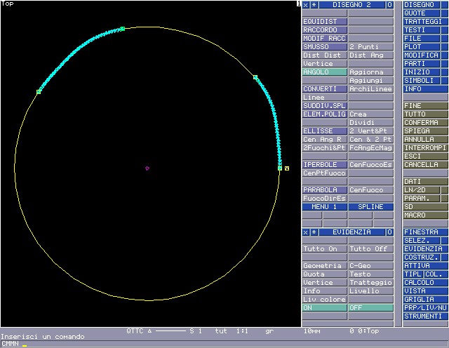
(window Cam PROFILES) saves a file Macro for CAD HP ME10 containing the B-SPLINE
The Macro Output can be directly made
from the
Menù File in ME10 or keystroking cmmn
corresponding to
the macro
loaded
during the start-up of the program.
DEFINE
Cmmn
LOCAL NAMEFILE
{This file '/CAM-SOFT/CMM2000/TMP/LAST' is automatically written by CMM2000 in manner to load the last Cam Profile generated}
OPEN_INFILE 1 '/CAM-SOFT/CMM2000/TMP/LAST'
READ_FILE 1 NAMEFILE
CLOSE_FILE 1
INPUT NAMEFILE
END_DEFINE
 INPUT macro CMMN in ME10
 Conversion BSPLINE in
Circle-Arcs+Lines or
Lines inside ME10
Conversion BSPLINE in
Circle-Arcs+Lines or
Lines inside ME10
(window 3D)
save the object selected in the IGES
3D format.
In order to select
the part to be saved as file IGES
3D click
on the single part or in a group
keeping pressed
the key SHIFT.
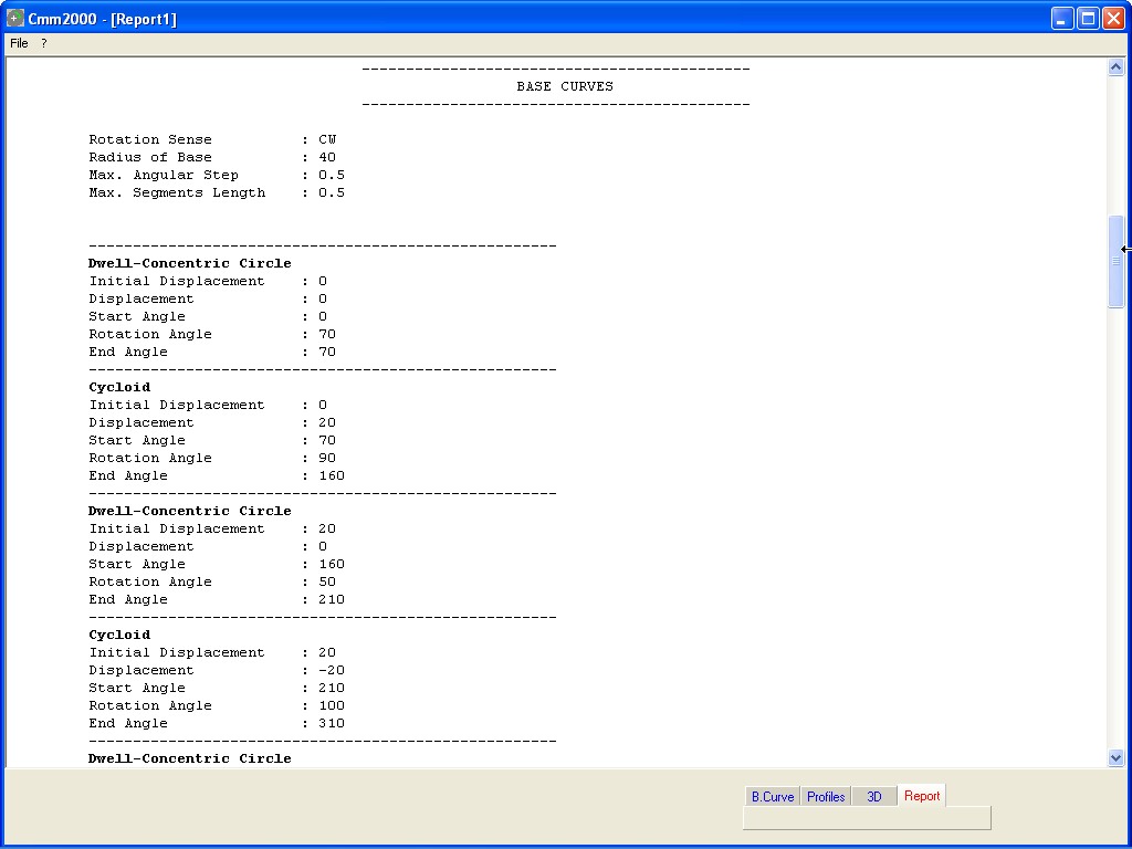
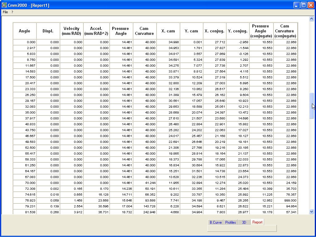
Gaining access to the window DATA, after generation of Cam Profile,
it is possible to visualize the summarizing data of the project.
It
is possible to optimize the HTML Report in order to store this file
all together the other useful files.
Inside Menù File (Top Bar) it is possible to select the command enabled to export Data in EXCEL format.
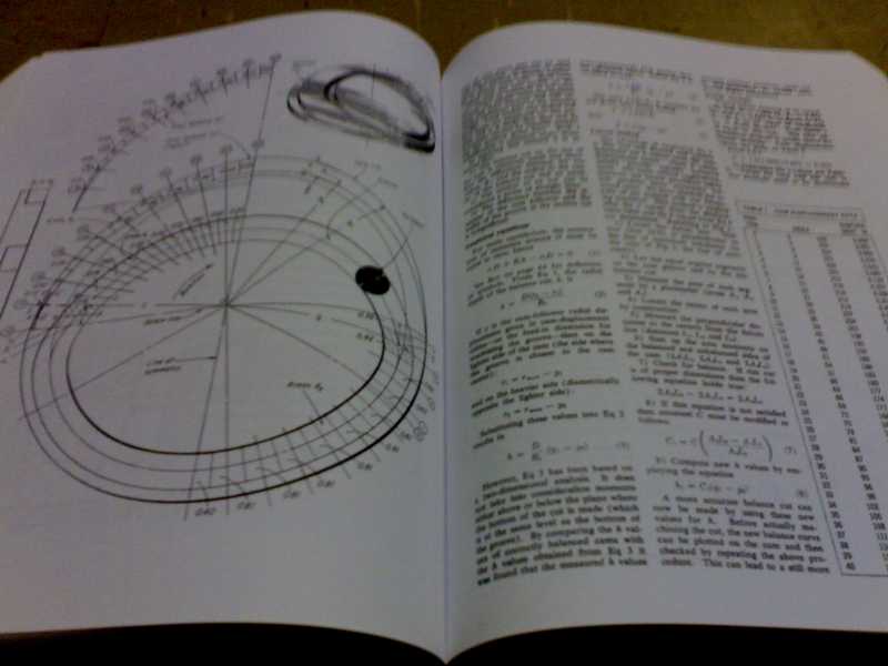
P. L. Magnani - G. Ruggieri ; "MECCANISMI PER MACCHINE AUTOMATICHE" Politecnico di Milano, Dipartimento di Meccanica ; UTET (Milano) 1986 H. A. Rothbart ; "CAMS DISIGN HANDBOOK" ; McGraw-Hill (New York) 2003
H. A. Rothbart ; "CAMS DISIGN, DYNAMICS AND ACCURACY " ; WILEY (New York) 1956
VDI-Handbuch Getriebetechnik I ; "BEWEGUNGSGESETZE FUR KURVENGETRIEBE, Theoretische Grundlagen" VDI 2143 Dusseldorf 1980
SOFT-MEC ; "MECAD Mechanisms Computer Aided Design" ; Hadbook - University of Brescia 1991
 Return at Home page.